Satec PM175 Manual User Manual
Browse online or download User Manual for Equipment Satec PM175 Manual. SATEC PM175 Manual User Manual
- Page / 168
- Table of contents
- BOOKMARKS
- Powermeter and Power 1
- Quality Analyzer 1
- LIMITED WARRANTY 2
- WARNING 2
- Table of Contents 3
- Features: 6
- Measured Parameters 8
- Chapter 2 Installation 10
- Chapter 2 Installation 11
- Mechanical Installation 11
- DIN Rail Mounting 13
- Remote Display Installation 14
- Special Cutout 15
- Electrical Connection 16
- Electrical Installation 18
- Terminals 19
- Power Source Connection 19
- Chassis Ground Connection 19
- Wiring Diagrams 20
- I/O Connections 25
- Analog Outputs 26
- Analog Inputs 26
- Communications Connections 27
- COM1 RS-422/485 Connection 28
- COM1 Ethernet Connection 29
- RS-485 MULTI-DROP CONNECTION 31
- Indicators and Controls 32
- Data Display 33
- Navigation Buttons 34
- Common Measurements Display 35
- Energy Display 38
- Status Display 39
- Using the Menus 41
- Entering the Password 42
- Selecting a Menu Entry 42
- THD/TDD 43
- Menu Operations 44
- Device Options 45
- Network Address 47
- Counters Setup 47
- Control Setpoint Setup 48
- Analog Inputs Setup 49
- Analog Outputs Setup 51
- Analog Expander Setup 52
- Timers Setup 53
- Display Setup 53
- Meter Security 54
- Setting the Device Clock 55
- Demands 56
- Configuration Database 57
- Setting up Communications 57
- Configuring a Modem 59
- Setting Up the Meter 60
- Authorization 61
- Setting Up the Ethernet 62
- General Meter Setup 63
- Basic Meter Setup 64
- Local Settings 67
- Using Digital Inputs 68
- Using Relay Outputs 69
- Programming Analog Inputs 71
- Programming Analog Outputs 73
- Using Counters 76
- Using Periodic Timers 77
- Using Control Setpoints 77
- Recording Setpoint Events 81
- Registers 82
- Configuring Recorders 86
- Conventional Data Log Files 88
- EN50160 Background 94
- Evaluation Techniques 95
- Methods of Evaluation 97
- Voltage Interruptions 99
- Temporary Overvoltages 99
- Series PM175 Powermeters 100
- Harmonic Voltage 101
- Interharmonic Voltage 101
- EN50160 PQ Recorder Setup 103
- EN50160 Advanced Setup 106
- Configuring Modbus 107
- Configuring DNP3 108
- Configuring DNP Class 0 110
- Remote Device Control 113
- Event Flags 114
- Device Diagnostics 114
- Updating the Clock 115
- Administration 117
- Upgrading Device Firmware 117
- Monitoring Devices 119
- Retrieving Log Files 120
- Viewing Recorded Files 122
- Event Log 123
- Filtering Events 124
- Customizing Reports 128
- Viewing the Data Log 129
- Viewing Waveforms 130
- Manual Converting 138
- Automatic Converting 139
- Environmental Conditions 140
- Construction 140
- Power Supply 140
- Input Ratings 140
- Relay Outputs 141
- Digital Inputs 141
- Optional Analog Inputs 141
- Optional Analog Outputs 141
- Communication Ports 142
- Real-time Clock 142
- Log Memory 142
- Display Module 142
- Standards Compliance 143
- Measurement Specifications 144
- Setpoint Triggers 146
- Setpoint Actions 148
- Data Logging 150
- Appendix F Data Scales 167
Summary of Contents
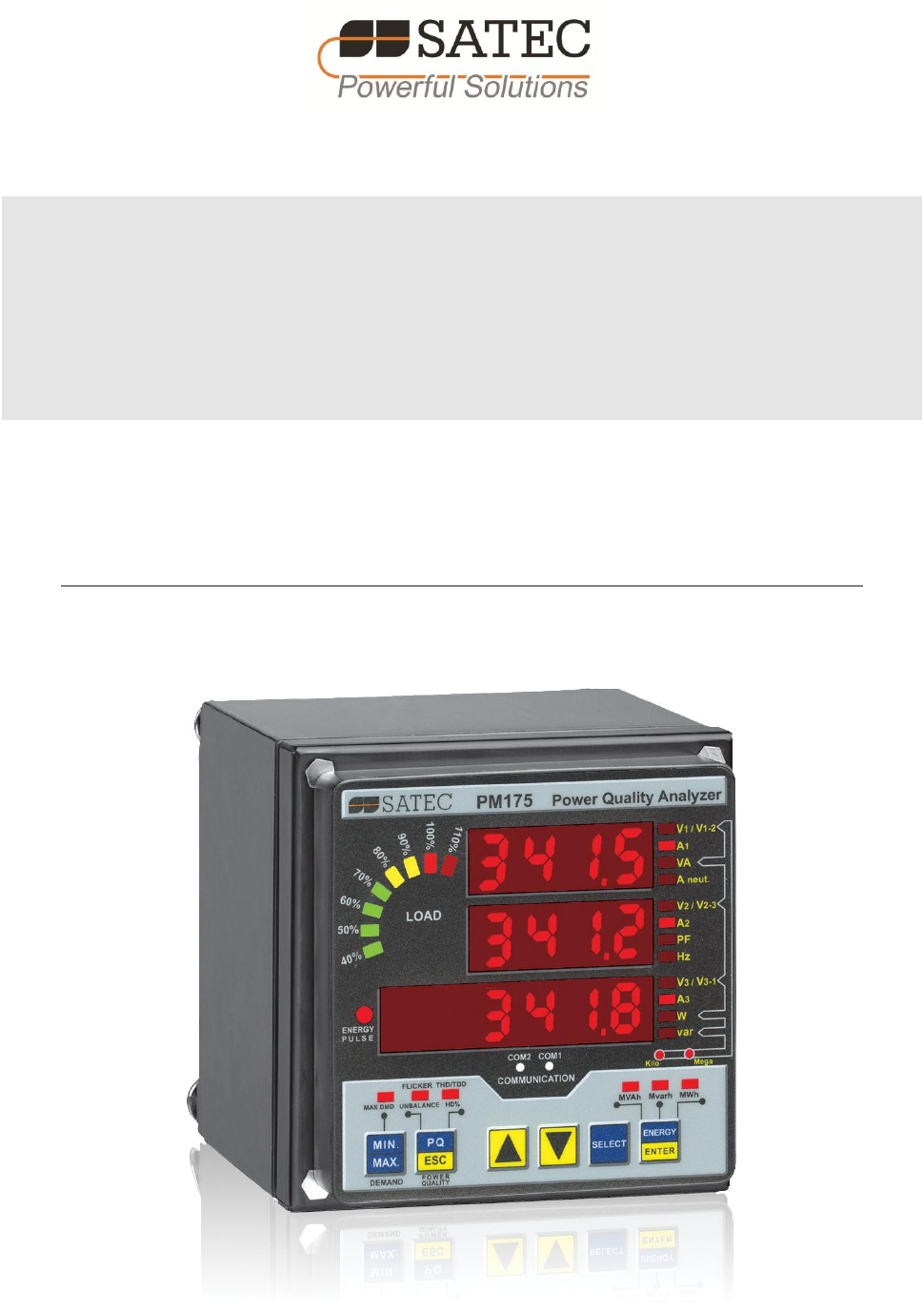
Series PM175 Powermeter and Power Quality Analyzer Installation and Operation Manual BG0415 Rev. A7
Chapter 2 Installation Mechanical Installation 10 Series PM175 Powermeters Chapter 2 Installation Mechanical Installation Panel Mounting Figu
Chapter 4 PAS Application Software EN50160 Evaluation and Recording 100 Series PM175 Powermeters and end on another phase. The fault magnitude is
Chapter 4 PAS Application Software EN50160 Evaluation and Recording Series PM175 Powermeters 101 Target Values The range of voltage unbalance give
Chapter 4 PAS Application Software EN50160 Evaluation and Recording 102 Series PM175 Powermeters Target Values The EN50160 does not provide targe
Chapter 4 PAS Application Software EN50160 Evaluation and Recording Series PM175 Powermeters 103 Reference Voltage As the general approach of the
Chapter 4 PAS Application Software EN50160 Evaluation and Recording 104 Series PM175 Powermeters To configure the PQ recorder: 1. Select Memory
Chapter 4 PAS Application Software EN50160 Evaluation and Recording Series PM175 Powermeters 105 Option Range Default Description On End Checked U
Chapter 4 PAS Application Software EN50160 Evaluation and Recording 106 Series PM175 Powermeters 2. Adjust limits you want to change. 3. Downlo
Chapter 4 PAS Application Software Configuring Communication Protocols Series PM175 Powermeters 107 Option Range Default Description Rapid Voltage
Chapter 4 PAS Application Software Configuring Communication Protocols 108 Series PM175 Powermeters Initially these registers are reserved and n
Chapter 4 PAS Application Software Configuring Communication Protocols Series PM175 Powermeters 109 The following table describes available DNP o
Chapter 2 Installation Mechanical Installation Series PM175 Powermeters 11 Figure 2-2 STEP 1 (ANSI 4" round cutout): Mount the display mod
Chapter 4 PAS Application Software Configuring Communication Protocols 110 Series PM175 Powermeters Parameter Options Default Description Frozen
Chapter 4 PAS Application Software Configuring Communication Protocols Series PM175 Powermeters 111 To view or change the factory-set DNP Class 0
Chapter 4 PAS Application Software Configuring Communication Protocols 112 Series PM175 Powermeters Protocol Setup from the Meter Setup menu and
Chapter 4 PAS Application Software Remote Device Control Series PM175 Powermeters 113 4. Check the “Ev On” box for the points you wish to be incl
Chapter 4 PAS Application Software Remote Device Control 114 Series PM175 Powermeters Event Flags The PM175 provides 8 common event flags that ar
Chapter 4 PAS Application Software Remote Device Control Series PM175 Powermeters 115 All diagnostic events are recorded to the Event log and can
Chapter 4 PAS Application Software Remote Device Control 116 Series PM175 Powermeters Resetting Accumulators and Clearing Log Files PAS allows yo
Chapter 4 PAS Application Software Administration Series PM175 Powermeters 117 Administration Changing a Password PAS allows you to remotely chang
Chapter 4 PAS Application Software Upgrading Device Firmware 118 Series PM175 Powermeters 4. Point to the firmware upgrade file for your meter,
Chapter 4 PAS Application Software Monitoring Devices Series PM175 Powermeters 119 Monitoring Devices Viewing Real-time Data Real-time data is co
Chapter 2 Installation Mechanical Installation 12 Series PM175 Powermeters Figure 2-5 STEP 3: Slide and position the meter on locating studs
Chapter 4 PAS Application Software Retrieving Log Files 120 Series PM175 Powermeters Viewing Real-time Waveforms The PM175 allows you to retrieve
Chapter 4 PAS Application Software Retrieving Log Files Series PM175 Powermeters 121 Check the Data log #9 and #10 boxes in the Select Logs dialo
Chapter 4 PAS Application Software Viewing Recorded Files 122 Series PM175 Powermeters Viewing Recorded Files Viewing Options Uploaded data can b
Chapter 4 PAS Application Software Viewing Recorded Files Series PM175 Powermeters 123 Filtering and Sorting Events To filter events, click on the
Chapter 4 PAS Application Software Viewing Recorded Files 124 Series PM175 Powermeters Filtering Events You can use filtering to find and work
Chapter 4 PAS Application Software Viewing Recorded Files Series PM175 Powermeters 125 Linking to Waveforms When displaying the PQ report, PAS es
Chapter 4 PAS Application Software Viewing Recorded Files 126 Series PM175 Powermeters To view the event details, click on the event point with
Chapter 4 PAS Application Software Viewing Recorded Files Series PM175 Powermeters 127 The standard compliance statistics is reported within the
Chapter 4 PAS Application Software Viewing Recorded Files 128 Series PM175 Powermeters Customizing Reports If you wish to add a logo image, head
Chapter 4 PAS Application Software Viewing Recorded Files Series PM175 Powermeters 129 Printing Reports To get a hardcopy of the report on the pri
Chapter 2 Installation Mechanical Installation Series PM175 Powermeters 13 DIN Rail Mounting The PM175 can be mounted on a 35-mm DIN rail. The dis
Chapter 4 PAS Application Software Viewing Recorded Files 130 Series PM175 Powermeters Viewing Data Trend To view data in a graphical form, clic
Chapter 4 PAS Application Software Viewing Recorded Files Series PM175 Powermeters 131 Click on the button on the local toolbar to view overlap
Chapter 4 PAS Application Software Viewing Recorded Files 132 Series PM175 Powermeters Selecting Waveform Channels To select the channels you w
Chapter 4 PAS Application Software Viewing Recorded Files Series PM175 Powermeters 133 Selecting the Time Axis The horizontal axis can be displaye
Chapter 4 PAS Application Software Viewing Recorded Files 134 Series PM175 Powermeters Viewing an RMS Plot Click on the button to open the RMS v
Chapter 4 PAS Application Software Viewing Recorded Files Series PM175 Powermeters 135 PAS can give you indication on whether harmonic levels in
Chapter 4 PAS Application Software Viewing Recorded Files 136 Series PM175 Powermeters Harmonics that exceed selected compliance levels are color
Chapter 4 PAS Application Software Viewing Recorded Files Series PM175 Powermeters 137 coordinated waveforms that have the same time span as the s
Chapter 4 PAS Application Software COMTRADE and PQDIF Converters 138 Series PM175 Powermeters COMTRADE and PQDIF Converters The COMTRADE and PQDI
Chapter 4 PAS Application Software COMTRADE and PQDIF Converters Series PM175 Powermeters 139 PQDIF file names contain a site name followed by a t
Chapter 2 Installation Remote Display Installation 14 Series PM175 Powermeters Remote Display Installation Mechanical Installation Standard Cutou
Appendix A Technical Specifications 140 Series PM175 Powermeters Appendix A Technical Specifications Environmental Conditions Operating tempera
Appendix A Technical Specifications Series PM175 Powermeters 141 5A secondary Operating range: continuous 10A RMS Burden: < 0.1 VA Overload wi
Appendix A Technical Specifications 142 Series PM175 Powermeters Communication Ports COM1 (Optional modules) Serial EIA RS-232 optically isolated
Appendix A Technical Specifications Series PM175 Powermeters 143 Standards Compliance Accuracy per ANSI C12.20 –1998 UL File no. E236895 Directiv
Appendix A Technical Specifications 144 Series PM175 Powermeters Measurement Specifications Parameter Full Scale @ Input Range Accuracy Range %
Appendix B Parameters for Analog Output Series PM175 Powermeters 145 Appendix B Parameters for Analog Output The following table lists parameter
Appendix C Setpoint Triggers and Actions 146 Series PM175 Powermeters Appendix C Setpoint Triggers and Actions Setpoint Triggers Display Code D
Appendix C Setpoint Triggers and Actions Series PM175 Powermeters 147 Display Code Designation Description ArPF.LG HI PF LAG AVR Low total PF Lag
Appendix C Setpoint Triggers and Actions 148 Series PM175 Powermeters Display Code Designation Description M.dAY DAY OF MONTH Day of month hour H
Appendix C Setpoint Triggers and Actions Series PM175 Powermeters 149 Display Code Designation Description FLG3.OFF CLR FLAG #3 Clear event flag #
Chapter 2 Installation Remote Display Installation Series PM175 Powermeters 15 Special Cutout Figure 2-11 Panel cutout dimensions Figure 2-12
Appendix D Parameters for Monitoring and Data Logging 150 Series PM175 Powermeters Appendix D Parameters for Monitoring and Data Logging The fo
Appendix D Parameters for Monitoring and Data Logging Series PM175 Powermeters 151 Designation Description kVA L2 kVA L2 kVA L3 kVA L3 PF L1 Power
Appendix D Parameters for Monitoring and Data Logging 152 Series PM175 Powermeters Designation Description I2 THD I2 Current THD I3 THD I3 Curren
Appendix D Parameters for Monitoring and Data Logging Series PM175 Powermeters 153 Designation Description I1 Mag I1 Current magnitude I2 Mag I2
Appendix D Parameters for Monitoring and Data Logging 154 Series PM175 Powermeters Designation Description V3 THD DMD V3/V31 THD demand 2 I1 THD
Appendix D Parameters for Monitoring and Data Logging Series PM175 Powermeters 155 Designation Description SUM REG2 Summary energy register #2 …
Appendix D Parameters for Monitoring and Data Logging 156 Series PM175 Powermeters Designation Description I3 %HD02 H02 Harmonic distortion … ...
Appendix D Parameters for Monitoring and Data Logging Series PM175 Powermeters 157 Designation Description kW L2 H01 kW L2 kW L3 H01 kW L3 kvar L
Appendix D Parameters for Monitoring and Data Logging 158 Series PM175 Powermeters Designation Description kvar MIN Total kvar kVA MIN Total kVA
Appendix D Parameters for Monitoring and Data Logging Series PM175 Powermeters 159 Designation Description kvar IMP SD MAX Maximum kW export slidi
Chapter 2 Installation Remote Display Installation 16 Series PM175 Powermeters Electrical Connection The remote display is connected to the meter
Appendix D Parameters for Monitoring and Data Logging 160 Series PM175 Powermeters Designation Description TOU REG1 TRF8 Tariff #8 register TOU R
Appendix D Parameters for Monitoring and Data Logging Series PM175 Powermeters 161 Designation Description TOU REG7 TRF1 Tariff #1 register TOU RE
Appendix D Parameters for Monitoring and Data Logging 162 Series PM175 Powermeters Designation Description TOU MAX DMD REG5 TOU Maximum Demand Re
Appendix E EN50160 Statistics Log Files Series PM175 Powermeters 163 Appendix E EN50160 Statistics Log Files The following table lists the EN501
Appendix E EN50160 Statistics Log Files 164 Series PM175 Powermeters Field No. Designation Description 9 N11 90%/1s Number of polyphase incidents
Appendix E EN50160 Statistics Log Files Series PM175 Powermeters 165 Field No. Designation Description 11 V2 N1 110% Number of incidents u>120%
Appendix E EN50160 Statistics Log Files 166 Series PM175 Powermeters Field No. Designation Description 3 N1 Number of polyphase incidents, N1 4
Appendix F Data Scales Series PM175 Powermeters 167 Appendix F Data Scales The maximum values for volts, amps and power in the PM175 setup and i
Appendix G Device Diagnostic Codes 168 Series PM175 Powermeters Appendix G Device Diagnostic Codes Diagnostic Code Description Reason 2 Memory
Chapter 2 Installation Remote Display Installation Series PM175 Powermeters 17 port settings must be as follows: Modbus RTU protocol, RS-485 inter
Chapter 2 Installation Electrical Installation 18 Series PM175 Powermeters Electrical Installation Before installation ensure that all incoming
Chapter 2 Installation Electrical Installation Series PM175 Powermeters 19 Terminals +RX16 RS-422/RS-485POWER SUPPLY-RX-TX +TXVN9 61413 15115V38H
2 Series PM175 Powermeters LIMITED WARRANTY The manufacturer offers the customer a 24-month functional warranty on the instrument for faulty workma
Chapter 2 Installation Electrical Installation 20 Series PM175 Powermeters Wiring Diagrams For AC input ratings, see “Technical Specifications” i
Chapter 2 Installation Electrical Installation Series PM175 Powermeters 21 Figure 2-18 4-Wire Wye 3-Element Direct Connection Using 3 CTs. Wiri
Chapter 2 Installation Electrical Installation 22 Series PM175 Powermeters Figure 2-20 3-Wire 2-Element Open Delta Connection Using 2 PTs, 2 CT
Chapter 2 Installation Electrical Installation Series PM175 Powermeters 23 This configuration provides accurate power measurements only if the vol
Chapter 2 Installation Electrical Installation 24 Series PM175 Powermeters Figure 2-23 4-Wire 3-Element Delta Direct Connection Using 3 CTs. Wir
Chapter 2 Installation I/O Connections Series PM175 Powermeters 25 I/O Connections For I/O ratings, see “Technical Specifications” in Appendix A.
Chapter 2 Installation I/O Connections 26 Series PM175 Powermeters Analog Outputs LOADSHIELD_+212V5OS/NCT.I1ATDIGITAL INPUTS90-264VAC50/60Hz85-29
Chapter 2 Installation Communications Connections Series PM175 Powermeters 27 Communications Connections Several communication options are availab
Chapter 2 Installation Communications Connections 28 Series PM175 Powermeters RS232 PM175 MALE CON. IBM PC/COMPATIBLE 25-PIN DB25 FEMALE CON. IB
Chapter 2 Installation Communications Connections Series PM175 Powermeters 29 COM1 Dial Up Modem Connection 05-12001-3AC0140 Figure 2-31 COM1: Tel
Chapter 1 General Information Series PM175 Powermeters 3 Table of Contents Chapter 1 General Information ...
Chapter 2 Installation Communications Connections 30 Series PM175 Powermeters COM2 RS-422/485 Connection -4-20mA98COM.1 :ATTENTIONDevicesStatic-S
Chapter 2 Installation Communications Connections Series PM175 Powermeters 31 UP TO 32 POWERMETERSCABLE MAXIMUM LENGTH 1000MRS485RS232RS485/422-23
Chapter 3 Display Operations Indicators and Controls 32 Series PM175 Powermeters Chapter 3 Display Operations Indicators and Controls Displa
Chapter 3 Display Operations Data Display Series PM175 Powermeters 33 Energy Pulse LED The PM175 has a red “Energy Pulse” LED. It flashes at a con
Chapter 3 Display Operations Data Display 34 Series PM175 Powermeters Primary and Secondary Volts Volts can be displayed in primary (default) or
Chapter 3 Display Operations Data Display Series PM175 Powermeters 35 Pressing both the UP and DOWN arrow buttons together returns to the first pa
Chapter 3 Display Operations Data Display 36 Series PM175 Powermeters Common Measurements (Main Display) 6 Ph.L1 PF kW/MW Phase L1 powers (if e
Chapter 3 Display Operations Data Display Series PM175 Powermeters 37 Min/Max and Maximum Demands 8 Hi In Hz kvar/Mvar Maximum neutral current
Chapter 3 Display Operations Data Display 38 Series PM175 Powermeters Individual Current Harmonics 39 40H I1 HD% I2 HD% I3 HD% Order 40 harm
Chapter 3 Display Operations Status Display Series PM175 Powermeters 39 Total and Phase Energies 12 Ac.En. IP.L3. MWh Phase L3 Wh import 13
Chapter 1 General Information 4 Series PM175 Powermeters Communication Ports ...
Chapter 3 Display Operations Status Display 40 Series PM175 Powermeters Status Display 4 rEL 1.2. 00 Relay status 5 St.In 1.2. 0
Chapter 3 Display Operations Using the Menus Series PM175 Powermeters 41 Using the Menus Navigation Buttons The PM175 has a menu-driven setup.
Chapter 3 Display Operations Using the Menus 42 Series PM175 Powermeters Entering the Password The Setup Change menu can be secured by a four-dig
Chapter 3 Display Operations Menu Operations Series PM175 Powermeters 43 2. Scroll through the parameter list with the UP and DOWN buttons unt
Chapter 3 Display Operations Menu Operations 44 Series PM175 Powermeters Label Parameter Options Default Description ConF Wiring connection (conf
Chapter 3 Display Operations Menu Operations Series PM175 Powermeters 45 Device Options This menu allows you to change the user-configurable devic
Chapter 3 Display Operations Menu Operations 46 Series PM175 Powermeters To select a setup option: 1. Press the SELECT button to activate the mi
Chapter 3 Display Operations Menu Operations Series PM175 Powermeters 47 Label Parameter Options Default Description Addr Device address Modbus: 1
Chapter 3 Display Operations Menu Operations 48 Series PM175 Powermeters 6. You are returned to the upper window to select another counter or ex
Chapter 3 Display Operations Menu Operations Series PM175 Powermeters 49 To exit the menu, press ESC. The following table lists available setpoint
Chapter 1 General Information Series PM175 Powermeters 5 Remote Device Control ...
Chapter 3 Display Operations Menu Operations 50 Series PM175 Powermeters Label Parameter Options Description Lo Zero scale 0-999,999 The low engi
Chapter 3 Display Operations Menu Operations Series PM175 Powermeters 51 Analog Outputs Setup This entry appears only if the meter is ordered with
Chapter 3 Display Operations Menu Operations 52 Series PM175 Powermeters Analog Expander Setup The meter can provide 16 additional analog outputs
Chapter 3 Display Operations Menu Operations Series PM175 Powermeters 53 Label Parameter Options Description Lo Zero scale Low engineering scale
Chapter 3 Display Operations Menu Operations 54 Series PM175 Powermeters Label Parameter Options Default Description UPdt Display update rate 0.1
Chapter 3 Display Operations Menu Operations Series PM175 Powermeters 55 1. Select “CtrL” in the upper window using the UP and DOWN arrow buttons
Chapter 3 Display Operations Menu Operations 56 Series PM175 Powermeters Label Option Format/Range Description dAY Day of week Sun = Sunday on =
Chapter 4 PAS Application Software Configuration Database Series PM175 Powermeters 57 Chapter 4 PAS Application Software Supplemental PAS softw
Chapter 4 PAS Application Software Setting up Communications 58 Series PM175 Powermeters your meter’s COM1 port can be equipped with an RS-232/RS
Chapter 4 PAS Application Software Setting up Communications Series PM175 Powermeters 59 2. In the “Protocol” box, select the same communication
Chapter 1 General Information Mechanical Installation 6 Series PM175 Powermeters Chapter 1 General Information The PM175 is a compact, mul
Chapter 4 PAS Application Software Setting Up the Meter 60 Series PM175 Powermeters 3. Click on the “IP address” and type in the IP address of
Chapter 4 PAS Application Software Authorization Series PM175 Powermeters 61 Downloading Setup to the Meter You can update each setup in your mete
Chapter 4 PAS Application Software Configuring Communications in your Meter 62 Series PM175 Powermeters To change the port settings in your mete
Chapter 4 PAS Application Software General Meter Setup Series PM175 Powermeters 63 The following table lists available network options. Paramete
Chapter 4 PAS Application Software General Meter Setup 64 Series PM175 Powermeters Basic Meter Setup Before operating your meter, provide the dev
Chapter 4 PAS Application Software General Meter Setup Series PM175 Powermeters 65 Parameter Options Default Description Demand Setup Power block
Chapter 4 PAS Application Software General Meter Setup 66 Series PM175 Powermeters The following table lists available device options. Paramete
Chapter 4 PAS Application Software General Meter Setup Series PM175 Powermeters 67 Power Calculation Modes The power calculation mode option allow
Chapter 4 PAS Application Software General Meter Setup 68 Series PM175 Powermeters Parameter Options Default Description Country Default, or coun
Chapter 4 PAS Application Software General Meter Setup Series PM175 Powermeters 69 The available options are shown in the following table. Parame
Chapter 1 General Information Mechanical Installation Series PM175 Powermeters 7 Event recorder for logging internal diagnostics events, contro
Chapter 4 PAS Application Software General Meter Setup 70 Series PM175 Powermeters The available relay options are shown in the following table:
Chapter 4 PAS Application Software General Meter Setup Series PM175 Powermeters 71 Parameter Options Default Description Retentive mode NO YES NO
Chapter 4 PAS Application Software General Meter Setup 72 Series PM175 Powermeters The available options are described in the following table. O
Chapter 4 PAS Application Software General Meter Setup Series PM175 Powermeters 73 Scaling Analog Inputs for 0-2 mA and ±2 mA The input scales for
Chapter 4 PAS Application Software General Meter Setup 74 Series PM175 Powermeters Scaling Non-directional Analog Outputs When programming scale
Chapter 4 PAS Application Software General Meter Setup Series PM175 Powermeters 75 Scaling Analog Outputs for 0-2 mA and ±2 mA The output scales f
Chapter 4 PAS Application Software General Meter Setup 76 Series PM175 Powermeters Option Range Description Output parameter See Appendix B Selec
Chapter 4 PAS Application Software General Meter Setup Series PM175 Powermeters 77 The following table lists available options. Option Range Defau
Chapter 4 PAS Application Software General Meter Setup 78 Series PM175 Powermeters user to define a logical expression based on measured analog a
Chapter 4 PAS Application Software General Meter Setup Series PM175 Powermeters 79 Option Range Description Delays Operate delay 0.1-999.9 sec The
Chapter 1 General Information Mechanical Installation 8 Series PM175 Powermeters Password security for setup parameters and resets via the fro
Chapter 4 PAS Application Software General Meter Setup 80 Series PM175 Powermeters Using Event Flags The PM175 provides 8 common binary flags, ca
Chapter 4 PAS Application Software General Meter Setup Series PM175 Powermeters 81 controller in order to give an indication on the expected event
Chapter 4 PAS Application Software Configuring Summary Energy and TOU Registers 82 Series PM175 Powermeters Configuring Summary Energy and TOU Re
Chapter 4 PAS Application Software Configuring Summary Energy and TOU Registers Series PM175 Powermeters 83 The available options are shown in the
Chapter 4 PAS Application Software Configuring Summary Energy and TOU Registers 84 Series PM175 Powermeters The daily profile setup allows you t
Chapter 4 PAS Application Software Configuring Summary Energy and TOU Registers Series PM175 Powermeters 85 The meter’s TOU calendar allows you t
Chapter 4 PAS Application Software Configuring Recorders 86 Series PM175 Powermeters Configuring Recorders The PM175 is provided with a 1-Megabyt
Chapter 4 PAS Application Software Configuring Recorders Series PM175 Powermeters 87 Option Range Description Size The memory size allocated to t
Chapter 4 PAS Application Software Configuring Recorders 88 Series PM175 Powermeters No. File Type Size, Bytes Channels Number of Records Number
Chapter 4 PAS Application Software Configuring Recorders Series PM175 Powermeters 89 1. Double click on the file partition with the left mouse bu
Chapter 1 General Information Mechanical Installation Series PM175 Powermeters 9 Parameter Display Comm. Analog Pulse Alarm kvarh Import per phase
Chapter 4 PAS Application Software Configuring Recorders 90 Series PM175 Powermeters automatically update the “Parameter” box with the following
Chapter 4 PAS Application Software Configuring Recorders Series PM175 Powermeters 91 3. Select the TOU Daily Profile file type. 4. Select the n
Chapter 4 PAS Application Software Configuring Recorders 92 Series PM175 Powermeters 3. Select the maximum number of records you want to be reco
Chapter 4 PAS Application Software Configuring Recorders Series PM175 Powermeters 93 7. Select the number of cycles to be recorded prior to the e
Chapter 4 PAS Application Software EN50160 Evaluation and Recording 94 Series PM175 Powermeters EN50160 Evaluation and Recording EN50160 Backgrou
Chapter 4 PAS Application Software EN50160 Evaluation and Recording Series PM175 Powermeters 95 interruptions less than 3 min Temporary overvoltag
Chapter 4 PAS Application Software EN50160 Evaluation and Recording 96 Series PM175 Powermeters declared by the EN50160 may differ for characteri
Chapter 4 PAS Application Software EN50160 Evaluation and Recording Series PM175 Powermeters 97 The PQ recorder is programmable to trigger the wav
Chapter 4 PAS Application Software EN50160 Evaluation and Recording 98 Series PM175 Powermeters A rapid voltage change is not classified if it cr
Chapter 4 PAS Application Software EN50160 Evaluation and Recording Series PM175 Powermeters 99 it becomes greater than the end threshold on all a
Related products and manuals for Equipment Satec PM175 Manual
 (24 pages)
(77 pages)
(10 pages)
(17 pages)
(24 pages)
(24 pages)
(77 pages)
(10 pages)
(17 pages)
(24 pages)
© 2020, manymanuals.com. All rights reserved. | 0.630 s |
 Manymanuals.com
 Manymanuals.de
 Manymanuals.fr
 Manymanuals.it
 Manymanuals.pl
 Manymanuals.cz
 Manymanuals.es
 Manymanuals-pt.com
Comments to this Manuals